Debugging Ground Alignment
The Ground Debug section exposes independent views for the controller fit, raycasts, and sampled normals. It also provides optional missing-ground warnings.
Click the ? button beside the section title to expand the complete color and marker guide in the inspector. This guide remains usable in Play Mode, where normal Unity tooltips may not appear.
Debug Switches
| Inspector switch | Serialized field | Display |
|---|---|---|
Draw Body + Legs Center |
drawSupportCenterGizmo |
Orange sphere and cross at the Body and Legs render-bounds center used as input to controller fitting. It is not necessarily the final controller center. |
Draw External Foot Raycasts |
drawFootGroundProbeGizmos |
Rays anchored to the generated external-foot contacts, successful-hit guide, and forward arrow. |
Draw Ground Normals |
drawGroundProbeNormals |
Yellow raw normals, magenta resolved normals, and the green blended alignment normal. |
Log Missing Ground Warnings |
logMissingGroundWarnings |
Logs sampling failures. Active probe misses require 0.5 seconds; configuration errors are immediate. Disabled by default. |
Ground Normal Debug Length changes only the displayed normal length. It does not change sampling or alignment.
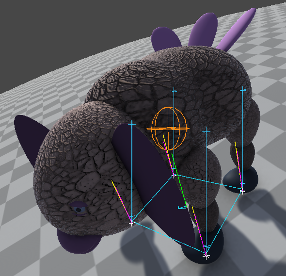
Four external-foot raycasts, their cyan support polygon and the normals displayed in the Unity debug view.
Reading Markers
- Cyan ray: the probe hit a collider in the selected ground layers.
- Cyan cross below a foot: its generated
GroundContactposition. - Cyan cross above a foot: the elevated ray origin.
- White cross: the exact successful ground hit.
- Red ray and cross: no valid collider was hit before the configured distance ended.
- Open support-guide edge: one of the adjacent external-foot probes missed.
Front Left Foot,Front Right Foot,Rear Right Foot, andRear Left Foot: Scene View labels for a Beast with at least two leg pairs.Left FootandRight Foot: Scene View labels for a one-pair Beast.- Cyan arrow: the Beast's forward direction.
In Game View, enable the Unity Gizmos button. Direction labels are available in Scene View only.
Nothing Is Displayed
Check the following:
- The relevant debug switch is enabled.
Align To Ground Slopeis enabled for ray and normal views.- The Unity Scene or Game View
Gizmosbutton is enabled. - The component and its GameObject are enabled.
- The application calls
DrawGroundProbeDebugLinesevery frame when Play ModeDebug.DrawLineoutput is required.
Draw Body + Legs Center can display independently of slope alignment.
The CharacterController Center Does Not Match The Orange Center
This can be expected. The orange gizmo shows the center of the Body and Legs render bounds. Automatic fitting then calculates the radius from the local X extent and enforces Unity's height >= 2 * radius capsule constraint. Finally, it places the capsule bottom at the bounds minimum.
On a wide, low Beast such as ePhant or Shardback, this can create a nearly spherical green controller gizmo whose center is well above the orange center. It does not mean that Head, Neck, or Tail renderers were included.
Compare the orange gizmo with Unity's green CharacterController gizmo. If the resulting gameplay envelope is unsuitable, disable Fit Controller On Start and set the application-owned controller dimensions manually. Otherwise, the automatic fit will overwrite those dimensions when Play Mode starts.
Every Ray Is Red
Verify Ground Alignment Layer Mask first. The terrain collider must be assigned to a layer included in that mask.
Then verify the vertical range:
Ground Probe Start Heightmust place the ray origin above the intended ground;Ground Probe Distancemust cover both the start height and the remaining gap to the ground;- very large or elevated Beasts may need a larger distance.
The ray origin and endpoint crosses show whether the failure comes from an incorrect origin or an insufficient distance.
Foot Probes Do Not Match The Stance
Enable Draw External Foot Raycasts and inspect the contact crosses, forward arrow, and foot labels.
Each ray is anchored to a generated GroundContact below the corresponding Foot. A Beast with one leg pair has two active probes. A Beast with more pairs still has only four: the front and rear left/right feet. Intermediate feet intentionally have no alignment ray.
After rebuilding or substantially reshaping a Beast, use Fit Controller To Beast, then inspect both the orange bounds center and Unity's green controller gizmo.
During Walk, Rush, or another leg animation, a contact follows its animated foot. Temporary misses are therefore possible. The last valid orientation is retained. Enable Log Missing Ground Warnings when diagnosing contacts: one warning appears only when every active probe misses continuously for at least 0.5 seconds, and a valid impact rearms it. Configuration errors such as an empty Layer Mask or missing generated contacts are reported immediately. The option is disabled by default to keep normal animation misses out of the Console.
The Beast Floats Or Sinks On Slopes
Enable these views together:
Draw Body + Legs Centerto verify that decorative parts do not shift the fitted center.Draw External Foot Raycaststo verify the sampled support feet.Draw Ground Normalsto compare raw, resolved, and blended normals.
Test the same Beast on flat ground, moving uphill, and moving downhill. Direction-dependent floating often indicates an incorrect rotation center or support sample. Constant vertical error is more likely to come from controller fitting, generated foot height, or another movement script applying an additional offset.
Long necks, heads, and tails are excluded from the support center. A Cowraffe should therefore retain the same locomotion center whether its neck is enabled or disabled.
Normal Lines Disagree
This can be expected:
- yellow shows the collider hit normal;
- magenta can use an interpolated Terrain or readable Mesh normal;
- green combines the available samples into the direction used for alignment.
For a MeshCollider, enable Read/Write on the source mesh when interpolated vertex normals are required. Otherwise the component falls back to the collider hit normal.
Release Builds
Disable debug switches when they are no longer needed. They are diagnostic views and should not be part of the normal application presentation.